
Patents for June/July 2023
USPTO Fastener Patents Compiled from the United States Patent and Trademark Office (USPTO) by the editor of Fastener Technology International for June 2023.
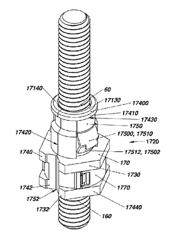
Fastener Assembly
US Patent 11655842
Published May 23, 2023
Inventor: Jürgen Rösing, Sehnde, Germany
Assignee: Fairchild Fasteners Europe—VSD GMBH, Niedersachsen, Germany
Disclosed is a fastener assembly comprising at least one of a bolt member and a nut member; and a
drive element adapted for engagement by an installation/driving tool, said drive element comprising a
body. The body of the drive element is joined either to the bolt member or to the nut member by
means of an interposed interlayer structure, the interlayer structure being adapted to fracture in
torsional shear and/or tensile stress in response to a relative rotational and/or tensile force applied to
the drive element with the installation/driving tool.
Structural Fastener
US Patent 11655841
Published May 23, 2023
www.uspto.gov
Inventors: Michael Walter Smith, Palatine, IL, USA; and Daniel James Dickinson, Lincolnshire, IL, USA
Assignee: MAG DADDY LLC, Wauconda, IL, USA
A spin nut is operable to attach to a threaded fastener such as a rod. The spin nut includes a threaded
nut having a shoulder for supporting a bracket, and a snap retainer detachably coupled to the
threaded nut operable to spin onto any position on the threaded rod. At least one wing is formed on
the snap retainer operable to attach to a bracket having a hole and spin to adjust to a position on the
threaded rod. The snap retainer is detachably couple the plurality of sectioned threaded nut sections
operable to spring open on a side opposite the band to allow the threaded rod to pass through.
Snap Nut Concrete Anchor Assembly
US Patent 11655846
Published May 23, 2023
Inventors: Manfred Droste, Limburg-Off heim, Germany; and Benjamin Schramm, Eppenrod, Germany
Assignee: Black & Decker Inc., New Britain, CT, USA The present disclosure describes an anchor device
for receiving and securing a shaft thereto. The device includes an outer housing within which a jaw
assembly is secured. The outer housing of the device may in turn be secured to or within a support
structure such as a building component. Jaw components of the jaw assembly may be threaded.
Furthermore, the jaw assembly has at least two confi gurations. In a fi rst confi guration, at least one
jaw component is positioned away from a central shaft axis against the biasing force of a biasing
member. A removable or reconfi gurable holding member or stop member selectively secures the at
least one jaw component in its position. In as second confi guration, the holding member is reconfi
gured by the inserted shaft to trigger movement of the at least one jaw component toward the central
shaft axis and into contact with the shaft.
Segmented Nuts
US Patent 11649846
Published May 16, 2023
Inventors: Brian Eric Bradshaw, Halls Head, Australia; Tom Peter Baskovich, Trigg, Australia; and Sam
William Turnbull, Spearwood, Australia
Assignee: Segnut Pty. Ltd., Mandurah, Australia A segmented nut has inner segments and an outer
sleeve. Part of the sleeve interface portion and part of the segment interface portion engage when the
sleeve rotates relative to the inner nut during release of the segmented nut with part of the segment
interface portion at a greater distance from a central axis of the segmented nut than a minimum
distance of the at least part of the sleeve interface portion from the central axis. One or more of the
segments can include a retainer preventing the sleeve moving toward a free face of the segment(s).
One or more of the segments can have a flange portion providing an increased working (compression)
face relative to a plain segmented nut. An assembled segmented nut can include some radial freeplay
for the segments to move radially whilst being retained within the sleeve prior to application of the
segmented nut to a threaded bolt, stud or rod such that threading of the segmented nut onto the
thread of the bolt, stud or rod removes the freeplay.
Mechanical Fastener System for Electromagnetic Effect (EME) Protection
US Patent 11649845
Published May 16, 2023
Inventors: Darrin M. Hansen, Seattle, WA, USA; Blake A. Simpson, Kent, WA, USA; Richard B. Tanner,
Seattle, WA, USA; and Peter K. Augusciak, Shoreline, WA, USA
Assignee: The Boeing Company, Arlington, VA, USA A mechanical fastener system for EME protection,
including at least one plated component, wherein the at least one plated component includes a base
material, a bonding layer disposed over the base material and a metal plating disposed over the
bonding layer.
Two-Part Nut with High Pressing Force
US Patent 11644059
Published May 9, 2023
Inventor: Dietmar Schnier, Garbsen, Germany
A nut has two parts, each having a section of an internal thread which is radially slidable onto an
external thread. The nut parts have cooperating connecting elements, which permit relative
displacement in a direction extending radially with respect to the axis of the internal thread until
reaching a use position in which the internal thread of the nut engages around the external thread
with a small clearance. The connecting elements have guide surfaces which guide the nut parts in a
rotational movement about an axis of rotation extending transversely to the axis of the internal thread
when displaced into the use position. Each nut part has at least one first locking arm which has on one
side a guide surface which induces the rotational movement when the nut parts are displaced and
bears against a complementary guide surface on a second locking arm of the other nut part.
Threaded Nut
US Patent 11644060
Published May 9, 2023
Inventors: Qingshui Ma, Fujian, China; Huosheng Zhan, Fujian, China; Dezheng Yu, Fujian, China; and
Chuanbao Zhu, Fujian, China
Assignee: Xiamen Lota International Co., Ltd., Fujian, China
The present disclosure discloses a threaded nut. The threaded nut comprises a body, a plurality of
threaded blocks, and a pushing cover. The body comprises a first through hole and a mounting cavity
connected to the first through hole. The plurality of threaded blocks is configured to move in the
mounting cavity in a radial direction. An inner wall of each of the plurality of threaded blocks is
disposed with an internal thread, and an outer wall of each of the plurality of threaded blocks is
disposed with a first inclined surface and a first straight surface. The pushing cover is disposed with a
second through hole, at least one second straight surface, and at least one second inclined surface.
Fastener
US Patent 11639735
Published May 2, 2023
Inventor: Masahiko Hamada, Aichi, Japan
Assignee: Aoyama Seisakusho CO., LTD., Niwa-gun, Japan
A fastener to fasten a member to be fastened includes a shaft portion, a tool working surface, and an
external operation restricting portion. The shaft portion is provided with a male thread configured to
be rotated about an axis line to work so as to fasten the member to be fastened. The tool working
surface is formed to a tool working portion integrated with the shaft portion. A tool to rotate the shaft
portion works to the tool working surface. The external operation restricting portion is configured to
restrict the rotation of the shaft portion through an operation from outside the fastener. In this
fastener, the tool working surface to which the tool works is formed in an approximately cylindrical
inner surface shape.
Fastener for Heavy Transmission Parts
US Patent 11635104
Published April 25, 2023
Inventors: Wim De Laet, Antwerp, Belgium; Jan Aerts, Friedrichshafen, Germany; and Dominiek
Ceyssens, Friedrichshafen, Germany
Assignees: ZF Friedrichshafen AG, Friedrichshafen, Germany; and ZF Wind Power Antwerpen N.V.,
Lommel, Belgium
A fastener for a transmission part includes a main body. The main body has at least one external
screw thread and at least one through-hole. The fastener further includes a first pin displaceable in a
first region of the through-hole and a second pin having an external screw thread. A second region of
the through-hole has at least one internal screw thread configured to be screwed to the external
screw thread of the second pin. The second pin has a through-hole. The first pin has an internal screw
thread aligned with the through-hole of the second pin.
Nut-locking Device and Associated Assembly Unit
US Patent 11629746
Published April 18, 2023
Inventors: Martial Broucke, Delincourt, France; Gildas Boleis, Lantic, France; Alan Philippe, Lamballe,
France; and Pierre Petit, Francheville, France
Assignee: LISI Aerospace, Paris, France
The invention concerns a unit (210) for a locking device, comprising: a nut (212) comprising two coaxial
taps in opposite directions; and a ring (213); said ring including a third tap (38); the first (18) and third
(38) taps being capable of engaging with a single first thread (22); said ring including a second thread
(40) capable of engaging with the second tap (20) of the nut. The unit further comprises a washer (214)
configured (274) so as to be inserted around one (212) of the nut and the ring, the washer comprising
an elastic engagement means (272) for engaging with the other (213) of the ring and the nut in an
installation position of the unit, so as to prevent the ring and the nut from rotating relative to each
other.
Profile Clamp with a Screw Having a Section of Reduced Diameter
Us Patent 11629737
Published April 18, 2023
Inventors: Rufei Ma, Qingdao, China; Shiwen Wang, Changzhou, China; and Gary Ives, Newbury, Great
Britain
Assignee: NORMA Germany GmbH, Maintal, Germany
A profile clamp includes a clamping band and a first tensioning head arranged at a first end and a
second tensioning head arranged at a second end of the clamping band. The first tensioning head
includes a first opening and the second tensioning head includes a second opening. A screw is
provided with a screw head and a screw body. The screw body may be guided through the first
opening and the second opening. A threaded nut is provided, which may be arranged on the screw
body when the screw body is guided through the first opening and the second opening. The screw
body has a first threaded section and a second threaded section and a section of reduced diameter
therebetween.
Captive Screw
US Patent 11629747
April 18, 2023
Inventors: Chong Tan, Spring, TX, USA; and Joseph Allen, Tomball, TX, USA
Assignee: Hewlett Packard Enterprise Development LP, Spring, TX, USA
A captive screw, comprising: a screw; a press fit nut, to connect to an opening on a device and to
accept a screw, including: a bottom portion, to extend through the opening; a top portion; and a
middle portion, wherein the middle portion is smaller in circumference than the top portion and the
bottom portion; and a sleeve including a protrusion, wherein the sleeve fits over the screw and
attaches to the press fit nut via the protrusion.
Screw
US Patent 11629745
Published April 18, 2023
Inventor: Ching-Cheng Chen, Kaohsiung, Taiwan
Vertex Precision Industrial Corp., Kaohsiung, Taiwan
A screw has a screw head and a shank extending downwardly from the screw head. The shank has a
threaded segment, a cutting segment, and a tapered segment sequentially arranged downwardly, a
thread spirally surrounding an external surface of the shank from the threaded segment to the
tapered segment, multiple cutting ribs arranged around the external surface of the shank on the
cutting segment of the shank, and multiple chip recesses formed between the cutting ribs. Each of the
cutting ribs has a rounded crest to enlarge a drill hole and to reduce a resistance formed between the
cutting ribs and the workpiece during drilling. The screw can be easily screwed into the workpiece with
less driving force.
Wing-shaped Thrust Screw Assembly
US Patent 11624392
Published April 11, 2023
Inventor: Wei-Chih Chen, Taichung, Taiwan
A thrust screw assembly includes a thrust screw and two threading dies for working the thrust screw.
The thrust screw includes a first shank, a second shank, an external thread, and a thrust member.
Each of the threading dies is provided with an external thread forming section and a flat portion
forming section. In a first molding process, the first shank is worked to form the thrust member with
two wing-shaped stop pieces. In a second molding process, the second shank is processed by the
external thread forming section of each of the two threading dies to form the external thread on the
second shank, and the two wing-shaped stop pieces is processed by the flat portion forming section of
each of the two threading dies to form two flat portions on the two wing-shaped stop pieces
simultaneously.
Fastening Nut Device
US Patent 11624397
Published April 11, 2023
Inventor: Daniel Stempfley, West Chester, OH, USA
A fastening nut device for fastening one substrate to another includes a cylinder, which is
circumferentially larger proximate to a first end thereof, thus defining a first section and a second
section of the cylinder. External threading, which is reversed, is positioned on the second section and
extends from a second end of the cylinder. The cylinder can be inserted into a first hole positioned in a
first substrate by counterclockwise rotation. The first section of the cylinder abuts a first face of the
first substrate and the second end of the cylinder is accessible from a second face of the first
substrate. A channel, which is internally threaded, extends into the cylinder from the second end. A
threaded fastener, which is engaged to a second substrate, can be inserted by clockwise rotation into
the channel to engage the second substrate to the second face of the first substrate.
Protective Covers for Weld-on Fasteners and Welding Processes Using
Cover-Protected Weld-On Fasteners
US Patent 11619254
Published April 4, 2023
Inventors: Christopher A. Michaels, Milford, MI, USA; and Lu Wang, Rochester Hills, MI, USA
Assignee: GM Global Technology Operations LLC, Detroit, MI, USA
Presented are protective covers for weldable fasteners, methods for making/using such coverprotected weldable fasteners, and motor vehicles with such covered fasteners welded to load-bearing
structural members. A weldable fastener assembly includes a fastener, such as a weld-on nut or clip
retainer, that is fabricated with a shank and a flange. One end of the shank has a fastener hole that
receives therethrough a mating fastener, such as a bolt, screw, stud or clip. The flange is formed, in
whole or in part, from a weldable material for welding to a load-bearing panel or other structural
support member. The flange may be integrally formed with and project radially outward from the
shank. A protective cover is attached to the flange and covers the fastener hole. The protective cover is
frangible and formed, in whole or in part, from a material designed to withstand the temperature at
which the weldable material melts.
Clinch Fastener
US Patent 11614118
Published March 28, 2023
Inventors: Steven P. Donovan, Roscoe, IL, USA; and Bryan D. Warju, II, Lake Orion, MI, USA
Assignee: Acument Intellectual Properties, LLC, Sterling Heights, MI, USA
A clinch fastener that includes a plurality of ribs disposed under a head of the clinch fastener, wherein
the ribs are specifically configured to displace host material more evenly than conventional clinch
fasteners. To that end, in cross section, along a line, arc, or combination, going from a central axis of
the clinch fastener to an outer periphery of the head of the clinch fastener, each rib preferably
provides a curved surface that is formed of multiple sections, wherein different radii define at least
two of the sections. The configuration of the ribs allows for a vented escape of host material beyond
the rib outside diameter and provides for radially focused material displacement, thereby releasing
stress within the host material and reducing warping during clinching.
Self-Punching Fastener
Patent 11608847
Published March 21, 2023
Inventors: Oliver Diehl, Usingen, Gemany; Tobias Jene, Friedrichsdorf, Germany; Amer Mahlme, Bad
Homburg, Germany; Christian Sowa, Muhlheim/Main, Germany; and Richard Humpert, Bad Nauheim,
Germany
Assignee: PROFIL Verbindungstechnik GmbH & Co. KG, Friedrichsdorf, Germany
The present invention relates to a self-punching functional element that is adapted for punching into a
workpiece, in particular into a sheet metal part. It comprises a head part forming a flange and having a
contact surface for contact with the workpiece; and a punching section that extends away from the
head part, in particular from the contact surface, and that is in particular arranged coaxially to a
central longitudinal axis of the functional element. The punching section has a peripheral punching
edge at its free end for punching through the workpiece and surrounds a cavity in a peripheral
direction, said cavity having an opening defi ned by the punching edge. An inner wall of the punching
section facing the cavity has at least one elevated slug securing portion projecting radially inwardly
into the cavity, in particular wherein the elevated portion has the form of a rib extending in an axial
direction.