
Patents for February/March 2023
Patents as compile by the editors for Fastener Technology International from USPTO in February.
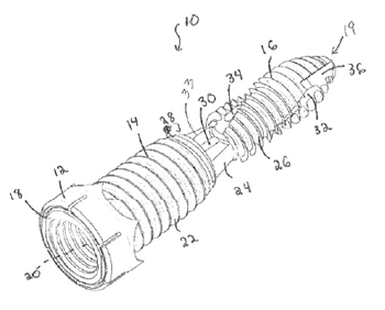
Bone Screw System and Method
US Patent 11553953
Issue January 17, 2023
Inventor: Joseph T. Robbins, Vestavia Hills, AL, USA
The present disclosure generally pertains to methods and systems for fusing a joint. The disclosure
includes mechanically immobilizing the joint by insertion of a bone screw, the bone screw including a
screw shaft operatively coupled to a screw head, the screw shaft including a longitudinal axis, a channel
extending along the longitudinal axis, a first shaft wall section, a second shaft wall section and a third
shaft wall section. Fusing of the joint includes inserting the screw into a first bone, a second bone and a
joint formed between the first bone and the second bone. Insertion further includes cutting bone pieces
away from the first bone using the third shaft wall section of the bone screw and directing the first bone
pieces into a helical depression formed in the third shaft wall section.
Washer for Secondary Battery, Secondary Battery Including Same, And Method for Manufacturing
Washer for Secondary Battery
US Patent 11557795
Issued January 17, 2023
Inventors: Byoung Gu Lee, Daejeon, South Korea; Do Gyun Kim, Daejeon, South Korea; Je Jun Lee,
Daejeon, South Korea; Sang Suk Jung, Daejeon, South Korea; and Hang Soo Shin, Daejeon, South Korea
Assignee: LG Energy Solution, Ltd., Seoul, South Korea
The present invention relates to a washer for a secondary battery including a film layer and an adhesive
layer disposed on at least one surface of the film layer, wherein the adhesive layer includes an adhesive
component and an indicator component, and the indicator component is fat-soluble, a secondary battery
including the same, and a method for manufacturing the washer.
Multi-Clinch Fastener Insert
US 11549531 January 10, 2023
Inventor: Jonathan Brunk, Philadelphia, PA, USA
Assignee: Penn Engineering & Manufacturing Corp., Danboro, PA, USA
An insert for the attachment of objects to composite or plastic panels consists of two parts, a retainer
and an insert. The retainer has a through-hole and knurls on its perimeter for gripping the walls of a
receiving hole in the composite or plastic panel. The insert has multiple self-clinching features at
increasing diameters, which when inserted into the retainer rigidly attach it to the retainer. The panel is
rigidly clamped between opposite sides of the panel by an enlarged head of the retainer and an opposing
flange on the insert. The selfclinching features of different diameter permit the device to be used with
panels of different thickness and allow a large tolerance range. A plain or threaded stud can be
substituted for the threaded hole of the insert. Both the retainer and the insert can be metallic.
Bolt and Method of Manufacturing the Same
US 11549544
January 10, 2023
Inventors: Kazuhiro Tsuzaki, Saitama, Japan; Toshitsugu Sakakibara; Saitama, Japan; and Kenichiro
Katsuki, Saga, Japan
Assignees: Honda Motor Co. Ltd., Tokyo, Japan; and Saga Tekkohsho Co., Ltd., Saga, Japan
A bolt includes a head portion on which a recess is formed. The recess has a bottom surface and a
sidewall extending from a periphery of the bottom surface. The sidewall has a lower end defined by the
bottom surface and includes an increased diameter portion and a reduced diameter portion. The
increased diameter portion has an inner diameter larger than an inner diameter of the lower end of the
side wall. The reduced diameter portion has an inner diameter smaller than the inner diameter of the
increased diameter portion. The reduced diameter portion is located opposite to the bottom surface
across the increased diameter portion.
Ergonomic Fastener with Snap-Fitting Leg and a Compression Collar
US Patent 11549541
Issued January 10, 2023
Inventors: Virginie Pouzols, Huningue, France; Grégory Paulin, Saint Martin d’Heres, France; and Jimmy
Voniez, Grenoble, France
Assignee: A. Raymond eT Cie, Grenoble, France
A fastener for attaching an element to a support includes a fastening base intended to pass through an
opening provided in the support by ways of an axial compression force, a head and a frustoconical and
elastically deformable compression collar. The collar, when compressed, is intended to bear against the
support. The collar is connected to the head in a connection region. The compression collar has a first
bending region, and at least a second bending region, the first and the second bending regions being
configured to deform in a predetermined manner when the fastener is subjected to the axial
compression force.
Fastener, Fastening Arrangement and Method for Mounting
US Patent 11549542
Issued January 10, 2023
Inventors: Daniel Gasser, Diepoldsau, Switzerland; and Thomas Heinzmann, St. Gallen, Switzerland
Assignee: SFS intec Holding AG, Heerbrugg, Switzerland
A fastening arrangement including a grommet, which is configured as a substantially cylindrical sleeve
with a head part, with a hollow-cylindrical shaft and with a conical tip, and also a fastener and a nut, for
example made of plastic, which is fitted on the first threaded portion of the fastener. The fastener has
two threaded portions, wherein one threaded portion is configured as a right-hand thread and the other
threaded portion is configured as a left-hand thread (or vice versa). Moreover, the invention comprises a
mounting method for such a fastening arrangement, in which the setting operation (anchoring of the
fastener, adjustment of the sheath) can be managed in one step without changing the driving direction of
the setting tool.
Drill Bit Structure of Self-Tapping Screw
US Patent 11549543
Issued January 10, 2023
Inventor: Hsiao-Wen Huang, Changhua, Taiwan
A drill bit structure of a self-tapping screw is rotated clockwise to screw with a workpiece or is rotated
counterclockwise to remove from the workpiece, and the self-tapping screw contains: a head, a shank
and a drill bit. The head is configured to connect with a tool. The shank integrally extends from the head.
A conical face has a tip, two arcuate grooves and two first cutting edges. Each of the first cutting edges is
formed on a connection portion of each arcuate groove and the conical face. The drill bit includes two
third cutting edges, and each third cutting edge is adjacent to the tip, shapes of the two first cutting
edges correspond to shapes of the two third cutting edges respectively, and heights of the two first
cutting edges are not less than the conical face. Each first cutting edge has a reinforcement portion.
Reduced Ring Groove Rivet
US Patent 11549539
Issued January 10, 2023
Inventors: Wen-Pin Chen, Taoyuan, Taiwan; and Magora Saquing Domingo Jr., Taoyuan, Taiwan
Assignees: Rodex Fasteners Corp., Taoyuan; and Goebel Innovative Entrepreneurial Company, Ratingen,
Germany
A reduced ring groove rivet at least includes a pin having a head and a body connected to the head; a
plurality of sets of ring grooves are equidistantly arranged on the body, and each of the sets of ring
grooves includes a first ring groove and a second ring groove adjacent to the first ring groove, wherein
the first ring groove has a first groove bottom and a first groove peak adjacent to the first groove bottom,
and the second ring groove has a second groove bottom and a second groove peak adjacent to the
second groove bottom; a diameter of the second groove bottom is smaller than a diameter of the first
groove bottom, or a diameter of the second groove peak is smaller than that of the first groove peak, so
that any of the plurality of sets of ring grooves can be breaking part during operation.
Pressure Lock Retention Fastener
US Patent 11549538
Issue January 10, 2023
Stephen M. Hill, Buckley, WA, USA
In implementations of a pressure lock retention fastener, the fastener assembly includes an insert sized
for insertion into a fastener hole in a first panel. The fastener assembly has a threaded collet sized to
slide in the insert and has expandable flanges that extend below the insert. The expandable flanges are
sized for insertion into an aligned hole in a second panel. The fastener assembly also includes a screw
installable through the insert to engage the threaded collet. The screw exerts a force that pushes the
expandable flanges outward as screw rotation drives the screw into the threaded collet, and ridge locks
of the expandable flanges seat up against the second panel effective to fasten the panels together. In
implementations, a plate is installable between the panels with slotted holes having antirotation tabs that
prevent a fastener assembly from spinning in the panel holes.
Fastening Assembly Including a Nut Holder and a Fastening Plate Fastened to a Substrate
US Patent 11542972
Issued January 3, 2023
Inventors: Philip Cresswell, Toulouse, France; and Julien Salomon, Toulouse, France
Assignee: Airbus Operations SAS, Toulouse, France
A fastening assembly suitable for being fastened to a substrate with a front face and a first hole. The
fastening assembly includes a fastening plate with a second plate with front and rear faces and pierced
with a second hole aligned with the first hole. The fastening plate front face is fastened to the substrate
rear face. The assembly includes a nut holder with a third plate with front and rear faces and pierced with
a third hole aligned with the second hole and a nut fastened to the third plate on the side of the rear face
and coaxial with the third hole. The front face of the nut holder is fastened to the rear face of the
fastening plate. The fastening plate includes a first fastener that engages with a second fastener of the
nut holder to removably fasten the nut holder to the fastening plate.
Locking Push-Pull Fastener Assembly
US Patent 11536310
Issued December 27, 2022
Inventors: Robert D. Schaefer, Huntington Beach, CA, USA; Andrew L. Bullard, Manhattan Beach, CA, USA;
Brian R. Schaefer, Huntington Beach, CA, USA; and Michael C. Barr, Torrance, CA, USA
Assignee: Raytheon Company, Waltham, MA, USA
A precision adjustment fastener mechanism comprises a base, a platform and a locking push-pull
fastener assembly. The base has a first aperture and the platform has a second aperture. The fastener
assembly is disposed within the second aperture. The fastener assembly comprises a clamping fastener
having a portion positioned in the first aperture, a sleeve having a third aperture extending along an axis
of the sleeve. The clamping fastener is positioned within the third aperture. The sleeve comprises a first
portion moveable relative to a second portion along the axis. The first portion and the second portion
each comprise outer threads. An axial displacement portion separates the first and second portions and
transmits a torque between the first and second portions. The axial displacement portion facilitates
movement of the first and second portions to bind threads of the first and second portions with the
threads of the platform.
Coupling Nut Visible Tightness Indicator
US Patent 11530762
Issued December 20, 2022
Inventors: Ryan K. Coello, Renton, WA, USA; Andrew B. Clements, Maple Valley, WA, USA; Ronald L.
Clements, Kent, WA, USA; David J. Linnenkamp, Renton, WA, USA; Christian J. Tom, Kent, WA, USA;
Christian M. Fedor, San Luis Obispo, CA, USA; and Donald W. Coffland, Seattle, WA, USA
Assignee: The Boeing Company, Chicago, IL, USA
A fitting assembly configured to visibly indicate nut tightness when coupling a first component to a
second component is disclosed. The fitting assembly comprises a nut comprising a threaded portion and
a chamber portion, wherein the chamber portion comprises one or more through holes. The fitting
assembly also comprises an indicator slidably disposed within the chamber portion, a retainer assembly
disposed within the chamber portion and configured to interlock with an inner surface of the nut, and a
spring disposed within the chamber portion between and engaging, the indicator and the retainer
assembly. The retainer assembly is configured to interface with the spring to retain the spring within the
chamber portion. The fitting assembly is configured to receive the first component and the second
component such that, when the nut is rotated, a visibility of the indicator through the one or more
through-holes changes.
Fastener Feedback Feature
US Patent 11519446
Issued December 6, 2022
Inventors: Scott Liebelt, Eau Claire, WI, USA; and Jason Zander, Roberts, WI, USA
Assignee: Illinois Tool Works Inc., Glenview, IL, USA
A fastener or grommet is configured to securely clamp together one or more components. The fastener
includes a body having a longitudinal axis and at least one wall. The body further includes two arms
extending from the body on opposite sides at a flexure joint. Each of the arms includes a feedback
feature that causes hesitation in the fastener during installation. The feedback feature further comprises
an arched profile that extends the entire width of each of the arms.
Nut Locking Device and Assembly for Mounting Same
US Patent 11519450
December 6, 2022
Inventors: Gildas Boleis, Lantic, France; Alan Philippe, Lamballe, France; Pierre Petit, Francheville, France;
and Martial Broucke, Delincourt, France
Assignee: LISI Aerospace, Paris, France
The invention relates to a locking device (300) comprising: a shaft (24) comprising a first thread (22); and
a nut (12) and a ring (13) to be assembled on the shaft; the nut comprising a first inner thread (18)
defining a first radial clearance with the first thread of the shaft; the nut further comprising a second
inner thread (20) in the opposite direction to the first inner thread, the ring (13) comprising a second
thread (40) defining a second radial clearance with the second inner thread of the nut; the ring
comprising a third inner thread (38) defining a third radial clearance with the first thread of the shaft. The
inner threads and the first and second threads have an identical and constant thread pitch; and each of
the second and third radial clearances is greater than the first radial clearance.
Advanced Nut and Bolt
US Patent 11519452
Issued December 6, 2022
Inventors: Donald C. Busby, Woodway, TX, USA; Richard Franklin, Hewitt, TX, USA; and James L. Wollard,
Waco, TX, USA
Assignee: Howmet Aerospace Inc., Pittsburgh, PA, USA
A fastener including a bolt having an elongated shank having a first end, a second end opposite the first
end and a threaded portion having an external bolt thread, the bolt thread including a bolt pitch. The
fastener includes a nut having a first end, a second end opposite the first end of the nut and an internal
nut thread extending between the first and second ends of the nut and adapted to engage threadedly
the bolt thread of the bolt. The nut thread includes a nut pitch and a hardness that changes gradationally
between the first and second ends of the nut. The bolt pitch of the bolt thread of the bolt is mismatched
with the nut pitch of the nut thread of the nut.