
Patents for October/November 2022
Patents as compiled by the editors of WCTI from United States Patent and Trademark Office (USPTO)
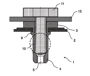
Self-Holding Screw Head
United States Patent 11,432,861
Issued September 6, 2022
Inventors: Nils Zander, Eckernforde, Germany; and Manfred Wieland, Kiel, Germany
Assignee: Stryker European Operations Holdings LLC, Kalamazoo, MI, USA
A screw insertion system has a screw having a threaded shaft and a head. The head has a conically tapered outer surface, the taper increasing in distance from a central longitudinal axis of the screw from a free end of the head towards a larger diameter adjacent the connection between the head and the threaded shaft. The conically tapered head outer surface has preferably two helically extending partially rounded threads. The head has a drive element for engaging a driver. A tubular screw holder has an outer surface and internal bore extending between a leading end and a trailing end for receiving the screw. The leading end having a conically tapered inner threaded portion for engaging the conically tapered outer thread of the screw head. The tubular screw holder outer surface having a diameter less than or equal to the maximum diameter of the conically tapered head.
Fastener for Thin Sheet Material
United States Patent 11,428,256
Issued August 30, 2022
Inventor: Michael Maloney, Doylestown, PA, USA
Assignee: Penn Engineering & Manufacturing Corp., Danboro, PA, USA
A fastener for thin panels has a shank with a deformable collar which works in conjunction with a configured mating panel to produce enhanced attachment forces, especially in the case of very thin panels. The mating panel is prepared with a round mounting hole with cross-cut openings or slots. The panel is stamped into a conical section in a preparatory step before installation to provide the fastener with snap-in engagement prior to final pressing. The fastener shank has an undercut located immediately below the collar which is snapped into the prepared hole. Once snapped in, a punch and flat anvil are used to press the deformable band of the fastener tightly against the prepared panel, capturing the panel rigidly between the deformable band and a base of the fastener. During pressing, the material of the fastener collar will also flow into the slots of the panel to prevent rotation.
Blind Rivet-Nut and Method for Securing a Component to a Carrier
United States Patent 11,428,260
Issued August 30, 2022
Inventor: Jens Linsel, Cologne, Germany
Assignee: Ford Global Technologies, LLC, Dearborn, MI, USA
A blind rivet-nut having an annular-flange-like setting head and a hollow shaft for securing a blind rivet-nut in an opening of a carrier. The hollow shaft has a free end having a threaded portion for receiving a threaded element of a tensioning tool. A clamping portion adjacent to the setting head forms a bead-like deformation when the tensioning tool is used to clamp the carrier between the bead-like deformation and the setting head. A threadless shaft portion is formed between the clamping portion and the threaded portion. The threadless shaft portion is threaded by a thread self-rolling or thread self-tapping fastener. The fastener is received in a positive-locking manner when the fastener is screwed into the thread formed on the previously threadless shaft portion. A method is also disclosed for securing a component to a carrier by a blind rivet-nut.
Flush-Break Blind Fastener
United States Patent 11,421,724
Issued August 23, 2022
Inventors: Jerry Quaresma, La Mirada, CA, USA; and David Littlejohn, Upland, CA, USA
Assignee: Monogram Aerospace Fasteners, Inc., Los Angeles, CA, USA
The fastener includes a bolt, a nut, a sleeve and a drive nut. The drive nut interfaces with the nut. The bolt is disposed through the nut, sleeve and drive nut. The bolt comprises one or more threaded portions and a non-threaded portion. The fastener breaks-off at the non-threaded portion during installation. The installed fastener comprises a recess-free, flush surface with a workpiece.
Blind Bolt and Tool Combination
United States Patent 11,421,722
Issued August 23, 2022
Inventors: Bruce A. Carmichael, Hinckley, OH, USA; and Michael Strange, Columbia Station, OH, USA
Assignee: Allfasteners USA, LLC, Medina, OH, USA
A blind bolt and tool is used for fastening a bolt through a hole in a structure when only one side of the structure is accessible. A receiver is formed on the tip end of a bolt shaft opposite from a bolt head. Internal threads are formed within the receiver proximate an outward end, and a hex socket is formed in the inward end of the receiver. External threads and a guide are formed on a tip of the tool, and the external threads mate with the internal threads in the receiver to hold the bolt during installation. A hex key on one end of the tool engages the hex socket in the receiver so that the tool may impose a torque on the bolt when a nut is being tightened on the bolt. In another embodiment, a splined tip is formed on the end of the bolt. The tip is designed to shear off when a sufficient torque is applied. Also, a shim is configured to fit between structures held together by the blind bolt.
Thread Form for Bone Screw
United States Patent 11,419,652
Issued August 23, 2022
Inventors: Jeffrey Wickham, Ooltewah, TN, USA; and Mark Dace, Collierville, TN, USA
Assignee: Warsaw Orthopedic, Inc., Warsaw, IN, USA
A bone screw including a head portion, a neck portion and a shaft portion is provided. The shaft portion includes a first end, an opposite second end, a helical thread form and a shank. The first end of the shaft portion is attached to the neck portion, and the helical thread form extends around the shank between the first end and the second end. The thread form terminates at a thread-termination surface adjacent the first end of the shaft portion, where the thread-termination surface affords an abrupt transition into the shank.
Expansion Bolt, and Connection Assembly Comprising Such an Expansion Bolt
United States Patent 11,415,158
Issued August 16, 2022
Inventor: Norbert Schneider, Ense-Niederense, Germany
Assignee: Heico GmbH, Ense-Niederense, Germany
An expansion bolt comprises a bolt having an end-face anchoring means for the tension-resistant anchoring of the bolt on or in a first assembly part, which bolt has a truncated-cone-shaped cone section and a bolt threaded section in its end section opposite to the anchoring means with a nut screwed thereon, an expansion sleeve having a cylindrical lateral surface and an inner cone contour interacting with the cone section of the bolt, and a clamping device supported on a second assembly part for widening the expansion sleeve and applying an axial clamping force to the assembly parts to be connected together. The cone section of the bolt is tapered in the direction toward its anchoring means and the inner cone contour of the expansion sleeve is tapered in the same direction. The expansion sleeve bears a clamping flange protruding outward in the radial direction on its end opposite to the inner cone contour. The clamping device comprises a clamping ring having an axial passage opening. The expansion sleeve engages through this passage opening, permitting an adjustability of the expansion sleeve in relation to the clamping ring in the axial direction, and protrudes with its clamping flange beyond a peripheral region of the clamping device enclosing the passage opening. The clamping ring also comprises multiple pressure bolts arranged circumferentially distributed, which mesh with their thread in internally threaded holes extending through the clamping ring in the axial direction and act with their bases indirectly or directly against the second assembly part to widen the expansion sleeve and apply an axial clamping force to the assembly parts. Furthermore, a connection assembly having such an expansion bolt is described.
Screw with Hole-Enlarging Portion
United States Patent 11,396,898
Issued July 26, 2022
Inventors: Kuo-Tai Hsu, Tainan, Taiwan; and Ming-Hao Hsu, Tainan, Taiwan
A screw includes a head and a shank extending from the head, and a hole-enlarging portion formed on the shank. The hole-enlarging portion features no thread and a substantially triangular transverse section. The hole-enlarging portion includes three inclined edges spaced from one another in the circumferential direction of the shank, and a guiding slope is formed between two adjacent inclined edges. The shank defines a longitudinal axis and is provided with a thread. Each inclined edge extends toward the head in an inclined direction relative to a horizontal axis perpendicular to the longitudinal axis. The inclined direction of each inclined edge is identical to a direction in which the thread extends toward the head.
Fastener and Methods of Manufacturing and Use
United States Patent 11,396,900
Issued July 26, 2022
Inventor: Blake A. Simpson, Chicago, IL, USA
Assignee: The Boeing Company, Chicago, IL, USA
The present disclosure provides a fastener. The fastener includes an elongated body having a first end and a second end opposite the first end. The fastener also includes a head having a first surface and a second surface opposite the first surface. The first end of the elongated body is coupled to the second surface of the head, and a diameter of the head is greater than a diameter of the elongated body. The fastener also includes a sleeve positioned over at least a portion of the elongated body and the second surface of the head. The fastener also includes a plurality of textured elements positioned on an exterior surface of the sleeve adjacent the second surface of the head. One or more of the plurality of textured elements extend from the exterior surface of the sleeve to the first surface of the head.
Wood Screw
United States Patent 11,391,313
Issued July 19, 2022
Inventor: Gerhard Hubmann, Graz, Austria
Assignee: Avvio GmbH & Co KG, Graz, Austria
A wood screw including a cylindrical screw shank, at the end of which there is formed a tip, a screw head, which is formed at the other end of the screw shank as well as a threaded section, which extends from the tip in the direction of the screw head, wherein the threaded section has a thread core and a thread winding having several threaded turns circulating the thread core, wherein several successive threaded turns have projections, which are formed alternatingly in essentially the direction of the screw head and in essentially the direction of the tip.