
USPTO Fastener Patents from December
USPTO Fastener Patents as Compiled from: United States Patent and Trademark Office (USPTO)
Automated Rivet Apparatus for Automated Installation of Semi-Tubular Fastener Rivets
United States Patent 11,185,912
Issued November 30, 2021
Inventors: Kip R. Kuldell, St. Charles, MO, USA; Christian E. Schaefer, Cottleville, MO, USA; Jeffrey J.
Kilwin, St. Peters, MO, USA; Tony S. Goddard, Tully, NY, USA; Thomas E. Burns, Sanborn, NY, USA;
Eugene T. Darlak, Lockport, NY, USA; and Jeffrey L. Foore, Cheektowaga, NY, USA
Assignee: The Boeing Company, Chicago, IL, USA
There is provided an automated rivet apparatus for installing a semi-tubular fastener rivet. The apparatus includes a numerical control (NC) drilling and riveting machine and a controller. The NC drilling and riveting machine includes a lower head having a lower pressure bushing, a lower drill spindle and a lower anvil to apply an upset force to a tail portion of the semi-tubular fastener rivet. The NC drilling and riveting machine further includes an upper head having an upper pressure bushing, an upper drill spindle and an upper anvil that holds the semi-tubular fastener rivet to insert the semi-tubular fastener rivet in a rivet-receiving hole. The lower drill spindle countersinks the rivet receiving hole from a lower side of a workpiece. The controller directs movement of a nose of the lower anvil to apply the upset force and form a predetermined flare contour in the tail portion within a lower countersink
Liner Bolt
Issued November 30, 2021
Inventor: Craig Oldnall, Atwell, Australia
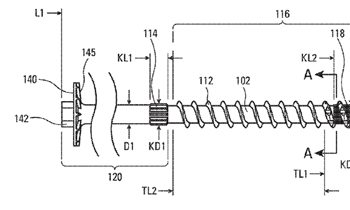
A liner bolt (10) comprising an elongate stud (12) and a head (14) engageable with a first end (16) of the stud (12). The head (14) including an inwardly tapered first end portion (24) adjacent a first end (21) thereof. A threaded portion (18) is provided adjacent a second end (17) of the stud for receiving a nut (20). The first end (21) of the head (14) includes an inwardly tapered opening (28) having an internal thread (30) and the first end (16) of the stud (12) includes an inwardly tapered end portion (32) having an external thread (34) such that the first end (16) of the stud (12) is engageable in the opening (28) in the head (14).
Variable Thread Knurl Fastener
United States Patent 11,181,138
Issued November 23, 2021
Inventor: Jeremy Scott Park, Bethpage, TN, USA
Assignee: Simpson Strong-Tie Company, Inc., Pleasanton, CA, USA
A fastener includes a shank having a point at a first end and a second, head end. A first portion of a thread is formed with a first thread angle and a second portion of the thread is formed with a second thread angle. One or more knurls are provided in the shaft in the threaded or unthreaded regions of the fastener. The thread may be serrated or jagged over one or more portions of the fastener, including the area of the first thread angle.
Fastener Retaining Component
United States Patent 11,174,890
Issued November 16, 2021
Inventors: Nathan Bjerke, Peoria, IL, USA; and Thomas Marshall Congdon, Dunlap, IL, USA Assignee:
Caterpillar Inc., Peoria, IL, USA
A fastener retaining component may comprise a first elongated member. A length of the first elongated member may be greater than a diameter of a fastener receiving element of a component. The fastener retaining component may further comprise a second elongated member. A length of the second elongated member may be greater than the diameter of the fastener receiving element. The fastener retaining component may be configured to be press-fi t within the fastener receiving element such that press-fitting the fastener retaining component, within the fastener receiving element, increases a tension in the fastener retaining component to cause the first elongated member and the second elongated member to engage with an inner surface of the fastener receiving element and to retain a fastener within the fastener receiving element.
Wood Screw and Method for Producing a Wood Screw
United States Patent 11,174,887
Issued November 16, 2021
Inventors: Patrick Roll, Schwabisch Hall, Germany; and Joachim Glattbach, Pfedelbach, Germany
Assignee: SWG Schraubenwerk Gaisbach GmbH, Waldenburg, Germany
The invention relates to a wood screw having a screw head having a drive configuration, a screw shank which emanates from the screw head and which at least in portions is provided with a thread, and a drilling tip which adjoins the thread, wherein the drilling tip is configured without a thread, wherein the drilling tip has two longitudinal cutters which continue up to a terminal point of the drilling tip and which run so as to be curved in relation to a central longitudinal axis of the screw, and wherein a circumference of the drilling tip between the two longitudinal cutters does not have any
further cutters.
Expansion Screw Structure
United States Patent 11,174,885
Issued November 16, 2021
Inventors: I-Fang Wang, Lukang Township, Taiwan Assignee: Masterpiece Hardware Industrial Co., Ltd.,
Lukang Township, Taiwan
An expansion screw structure contains an anchor for mating with a screw. The anchor includes a first segment and a second segment which have a central axis and a shank. The anchor further includes a head which has a slot. The shank includes a first threaded section, multiple cutouts, a decreasingly conical tip, a second threaded section, a slit, a first support foot, a second support foot. The slit has a first part, a second part and a third part. The second part has a first raised portion, the second part has a second raised portion, and the third part has a connection section and a thin coupling strap. The thin coupling strap has a first thickness, the connection section has a second thickness, and the first thickness of the coupling strap is 1/3 of the second thickness of the connection section.
Multi-Piece Anti-Vibration Locking Fastener
United States Patent 11,168,729
Issued November 9, 2021
Inventor: Earl Allen Size, Jr., Rochester Hills, MI, USA
A three-piece locking fastener including an interiorly threaded intermediate component open at opposite ends. A first screw having a first exterior thread pattern rotationally inter-engages with the interior threads of the intermediate component when installed through a first selected one of the opposite ends, the first screw having a hollow shaft exhibiting a further plurality of interior threads matching a direction of the first thread pattern. A second screw has a second exterior thread pattern opposite the first pattern and, upon being installed within the other selected one of the opposite ends, rotationally inter-engages the interior threads of the first screw, so that loosening of either of the first and second screws being prevented by their counter-threaded orientation.
Reduced Shank Fasteners
United States Patent 11,168,726
Issued November 9, 2021
Inventor: David Poster, Arlington, TX, USA
Assignee: Textron Innovations Inc., Providence, RI, USA A fastener includes: a shaft having longitudinal axis and a first and second threaded portions, the first and second threaded portions separated by a central portion having a reduced diameter between the first and second threaded portions, and at least one of the first or second threaded portions is chamfered to reduce friction on leading threads.
Thread-Forming Screw
United States Patent 11,156,248
Issued October 26, 2021
Inventors: Georg Vogel, Ingelfi ngen-Eberstal, Germany; and Jan Buchle, Pfedelbach, Germany
Assignee: Arnold Umformtechnik GmbH & Co. KG, Forchtenberg-Ernsbach, Germany
A thread-forming screw which is provided in particular for thin, perforated sheet metal contains a threaded shank which below the screw head is initially configured so as to be cylindrical and then continues to a conical forming portion. The screw shank within the forming portion has a rib forming an incomplete counter thread.
Fastener Assembly Having a Component-Isolating Grommet
United States Patent 11,149,768
Issued October 19, 2021
Inventors: Chad M. Clark, Stamping Ground, KY, USA; Ronald Owens, Lawrenceburg, KY, USA; Michael
Fullerton, Clarkston, MI, USA
Assignee: Illinois Tool Works Inc., Glenview, IL, USA
A fastener assembly is configured to securely couple to a component. The fastener assembly includes a compression-limiting bushing, a fastener coupled to the bushing, and a grommet coupled to the bushing. A clearance gap is defined between one or both of the bushing or the fastener and the grommet. At least a portion of the grommet is configured to move into the clearance gap as the fastener assembly is urged into an opening of the component. The grommet is configured to securely couple to the component.
Hidden Fastener Unit and Related Method of Use
United States Patent 11,149,445
Issued October 19, 2021
Inventors: Roger A. Vandenberg, Hudsonville, MI, USA; and Todd E. A. Schwartzkopf, Hudsonville, MI, USA Assignee: National Nail Corp., Grand Rapids, MI, USA
A fastener unit and related method for securing a board to a support is provided. The fastener unit includes a spacer block, a grip element extending from the spacer block and configured to fit in and engage a groove of the board, and one or more resilient compression elements joined with the spacer block. The resilient compression elements can be vertically compressible so at least a portion of it can move from an open mode to a compression mode and fi t within, then forcibly expand within, the groove, thereby securing the spacer block in a position adjacent the groove to establish a gap between the board and another board. Related methods of use also are provided.
Hardware Fastener with Movable Threaded Element and One or More Spring-Like Members
United States Patent 11,148,213
Issued October 19, 2021
Inventors: Alan J. Bookheimer, Greensboro, PA, USA; Ruy Frota de Souza Filho, Latrobe, PA, USA; Jason Won Goldsmith, Greensburg, PA, USA; and Jeremy P. Canonge, Pittsburgh, PA, USA Assignee:
Kennametal Inc., Latrobe, PA, USA
A hardware fastener with a movable threaded element suspended within a cavity formed in a body. The movable threaded element has an internal surface with threads for cooperating with a threaded fastener. The movable threaded element is suspended in the cavity by the one or more spring-like members such that an area, A, of reduced stiffness is created in the cavity proximate the movable threaded element, thereby allowing the movable threaded element to move a predetermined distance within the cavity when torque is applied to the threaded fastener. The one or more spring-like members store elastic potential energy to prevent the loss of pretension of the threaded fastener that can be caused by heat or vibration. The invention also eliminates the need for a torque wrench when tightening the threaded fastener to a specified torque value.
Intelligent Bolts and Methods of Their Use
United States Patent 11,149,777
Issued October 19, 2021
Inventors: Csaba Madru, Haljarp, Sweden; and Matts Lilja, Helsingborg, Sweden
Assignee: Strain Labs AB, Stockholm, Sweden
An intelligent bolt includes a head region and a threaded region. The head region includes a bolt cavity. A distance between the head region and a bottom end of the cavity changes in operation as a function of longitudinal stress applied between the threaded region and the head region, and the bolt includes a sensor arrangement for measuring changes in the distance. A distal end of the sensor arrangement is disposed adjacent to the bottom end, wherein changes in spatial position of the bottom end relative to the distal end occur as a function of changes in the stress applied to the bolt to defi ne a gap “G” whose size varies depending upon the stress. Interrogating radiation transmission in operation via the gap “G” from a source to a corresponding radiation sensor of the arrangement generates a stress measurement signal that is processed for wireless communication.
Easily Removeable Push-On Spring Nut
United States Patent 11,149,775
Issued October 19, 2021
Inventors: Michael Maloney, Doylestown, PA, USA; and Jonathan Brunk, Philadelphia, PA, USA
Assignee: Penn Engineering & Manufacturing Corp., Danboro, PA, USA
A fastener is installed by applying an axial pressing force onto a mating component such as a round pin or a square tab. The fastener includes spring arms formed by bent tabs which deflect when pressed onto and grip the pin or other mating component between jaws of the arms making the fastener resistant to being pulled off . Downward facing fingers located around the periphery of the fastener flex when they come into contact with another portion of the mating component. This creates a residual clamp load between the fastener and the component. The fastener can easily be removed using a tool similar to snap ring pliers or needle nose pliers. Two holes on opposite sides of the fastener allow the part to be squeezed and deformed into an oval shape. This action disengages the arms and allows the fastener to slide off the mating component without resistance.
Two-Piece Blind Fastener
United States Patent 11,143,226
Issued October 12, 2021
Inventor: Terry Vovan, Upland, CA, USA
Assignee: SPS Technologies, LLC, Jenkintown, PA, USA
A blind fastener for connecting panels includes a bolt and nut. The bolt includes a shaft, bolt head, and lug. The bolt head is between the shaft and lug. The shaft defines external threads opposite the bolt head. The lug includes a first tool engagement portion and first frangible portion that connects the
lug and bolt head. The nut includes a sleeve, nut head, and handling member. A central bore of the sleeve receives the shaft and defines internal threads mated with the external threads. The nut head is between the handling member and sleeve. The nut head extends radially from the sleeve and defines a recess that receives the bolt head. The handling member surrounds a portion of the lug. The handling member includes a second frangible portion and a second tool engagement portion. The second frangible portion couples the second tool engagement portion to the nut head.
Wood Screw
United States Patent 11,137,012
Issued October 5, 2021
Inventors: Kuo Tai Hsu, Tainan, Taiwan; and Ming Hao Hsu, Tainan, Taiwan
A wood screw that includes a head and a shank is revealed. The shank is formed by a main shank portion and a tapered portion whose diameter is smaller than that of the main shank portion, both provided with a locking thread. A plurality of drilling units, whose outside diameter of the drilling unit is smaller than that of the locking thread, is disposed on the tapered portion. The drilling units first destroy workpiece material corresponding to the main shank portion so that the workpiece material becomes loose and the resistance of the locking thread of the main shank portion is reduced. Thereby the wood screw is screwed into the workpiece more smoothly. Moreover, an internal thread segment whose thread depth matches that of the locking thread of the main shank portion is formed so that the wood screw and the workpiece are fastened more firmly.