
Patents for February
USPTO Fastener Patents Compiled from the United States Patent and Trademark Office by the editors of FTI
Fastening System, a Fastener Assembly, and a Method of Preloading the Fastener Assembly
US Patent 12203499
Published January 21, 2025
Inventors: Adam Ian Nadel, Vienna, VA, USA; and Kjersta Lynn Larson-Smith, Seattle, WA, USA
Assignee: Boeing Company, The, Arlington, VA, USA
A fastening system includes a first component and a second component. The fastening system includes a fastener assembly configured to attach together the first component and the second component. The fastening system also includes a layer disposed between the fastener assembly and the first component and/or the second component. The layer is configured to provide an alert when a predetermined compressive load has been reached in the first component and the second component which signals that a preload of the fastener assembly has been reached. A method of preloading a fastener assembly includes applying a torque to the fastener assembly until a predetermined compressive load has been reached in the first component and the second component. The alert of the layer is activated when the predetermined compressive load has been reached which signals that the preload of the fastener assembly has been reached.
Systems, Apparatuses, and Methods for Fasteners in Board Sports
US Patent 12201892
Published January 21, 2025
Inventors: Joseph Pulsifer, Atascadero, CA, USA; and Yuche Su, Taipei, Taiwan
Assignee: Mesa Distribution, Inc., Los Alamitos, CA, USA
Systems, apparatuses and methods for fastening components of equipment, specifically a skateboard, among other types of sporting boards or sports apparatuses or wheeled sporting apparatuses. Fastening systems disclosed herein may be utilized to couple a deck of a skateboard to a truck of a skateboard. The fastening systems may reduce the need for a tool (e.g., a hex drive or other tool) that might typically be utilized to engage a head of a fastener to hold the fastener in place while a securement body (e.g., a nut) is coupled to the fastener.
Captive Fastener and Method of Assembling the Same
US Patent 12203500
Published January 212, 2025
Inventors: Jingyao Peng, Shenzhen, China; Thomas V. Aukzemas, Lincoln University, PA, USA; Xuexian Qin, Shenzhen, China; Richard E. Schlack, Newark, DE, USA; Bing Hua Chiang, Taiwan, China; Chuanjun Li, Xiantao, China; and Xiaoying Liao, Dongguan, China
Assignee: Southco, Inc., Concordville, PA, USA
A captive fastener attachable to a panel along a fastener axis is provided. The captive fastener includes a fastener having a head portion and a shaft extending from the head portion and along the fastener axis. The captive fastener also includes a knob having a proximal end portion engaged to the head portion of the fastener and an annular portion extending radially around the fastener axis and the shaft of the fastener. A ferrule is associated with the knob, the ferrule defining an opening extending along the fastener axis and receiving the shaft of the fastener. The ferrule has a proximal end portion configured to prevent separation of the knob from the ferrule along the fastener axis and a distal end portion configured for engagement to the panel. A spring is positioned to bias the knob or the fastener proximally relative to the ferrule and to inhibit tilting of the knob or the fastener relative to the fastener axis. The proximal end portion of the ferrule having been positioned to be associated with the knob in an insertion direction along the fastener axis, and the head portion of the fastener having been inserted within the knob for engagement to the knob in the insertion direction. The engagement between the proximal portion of the knob and the head portion of the fastener is configured to resist axial movement of the knob relative to the fastener along the fastener axis, rotational movement of the knob relative to the fastener about the fastener axis, and pivotal movement of the knob relative to the fastener axis.
Steel For Bolts, and Method of Manufacturing Same
US Patent 12203149
Published January 21, 2025
Inventor: Masafumi Tada, Tokyo, Japan
Assignee: JFE Steel Corporation, Tokyo, Japan
Disclosed is a non-heat-treated steel that has low deformation resistance during cold forging in bolt head forming and excellent product yield, and that can be manufactured without the need to perform heat treatment for controlling strength variation. The disclosed steel has a chemical composition containing C: 0.18-0.24%, Si: 0.10-0.22%, Mn: 0.60-1.00%, Al: 0.010-0.050%, Cr: 0.65-0.95%, Ti: 0.010-0.050%, B: 0.0015-0.0050%, N: 0.0050-0.0100%, P: 0.025% or less inclusive of 0, S: 0.025% or less inclusive of 0, Cu: 0.20% or less inclusive of 0, and Ni: 0.30% or less inclusive of 0, in a range satisfying: 0.45≤C+Si/24+Mn/6+Ni/40+Cr/5≤0.60 and N≤0.519Al+0.292Ti, with the balance being Fe and inevitable impurities; and a microstructure in which bainite is present in an area ratio of 95% or more, where the microstructure contains prior austenite grains with a grain size number of 6 or more, and strength variation is 100 MPa or less.
Nutless Bolt
US Patent 12196244
Published January 14, 2025
Inventor: Brian Davies, Western Australia, Australia
Assignee: Metso Outotec Finland Oy, Tampere, Finland
A nutless bolt 10 for fastening a wear plate 12 to a structure 14 comprises a body 16 having a shaft 18 and a stop 20 coupled to the shaft 18. Shaft 18 is dimensioned to pass through a hole 22 in structure 14 while stop 20 is configured to stop the body 16 from falling wholly into or through the hole 22, and to engage with the wear surface plate. An axial bore 24 is formed in body 16 and houses locking balls 58 and a rod 28. The body 16 also has radial channels along which the balls 58 can roll. The rod 28 has a tapered portion 70 which increases in outer diameter from a first location L1 to a second location L2. In use the balls 58 are initially at the first location L1 on the rod 28 and partially within respective channels 56. Pulling the rod 28 in an up-hole direction results in the rod 58 moving in a radial outward direction as they roll along the tapered portion 70 to the location L2. The balls now lie partially outside of the of the body 16 locking the bolt 10 in the hole 22. Applying additional pulling force on the rod increases tension in the rod to intentionally cause a controlled break or separation of the rod into a first portion 72 that is withdrawn from the bore and a second portion 62 that remains in the bore and bearing against the balls.
Thread Forming and Thread Locking Fastener
US Patent 12196241
Published January 14, 2025
Inventors: Edmund A. Hebert, Mattapoisett, MA, USA; Kenneth J. Gomes, Portsmouth, RI, USA; Dennis O. Boyer, Bristol, RI, USA; John R. Reynolds, South Dartmouth, MA, USA; Donald A. Fosmoen, Portsmouth, RI, USA; and Benjamin M. Fosmoen, Coventry, RI, USA
Assignee: Research Engineering & Manufacturing, Inc., Middletown, RI, USA
A combined thread forming and thread locking fastener is disclosed. A fastener includes three thread zones. A first thread zone utilizes a first thread forming thread profile with an increasing outer diameter. A second thread zone extends from the end of the first zone utilizing the first thread forming thread profile and continues with a constant diameter. The third thread zone utilizes a thread locking thread profile continuing along substantially the remainder of the shaft of a fastener.
Method for Making Screw Hole
US Patent 12194555
Published January 14, 2025
Inventors: Fumihiko Inoue, Chuo-ku, Japan; and Masatsugu Hirose, Kobe, Japan
Assignee: TMEIC Corporation, Chuo-ku, Japan
A method for making a screw hole in a workpiece including a plate-shaped portion includes: preparing an auxiliary member having a flat plate shape; forming, in the plate-shaped portion, a first pilot hole having a minor diameter smaller than a major diameter of the screw hole; forming, in the auxiliary member, a second pilot hole having a minor diameter smaller than the major diameter of the screw hole; fixing the auxiliary member to the plate-shaped portion so that the first pilot hole is concentric with the second pilot hole; and making the screw hole in the plate-shaped portion and the auxiliary member by inserting a tap in the first pilot hole and the second pilot hole.
Androgynous Fastener
US Patent 12196245
Published January 14, 2025
Inventors: Olivia Irene B. Formoso, Santa Clara, CA, USA; Christine Elizabeth Gregg, San Mateo, CA, USA; Greenfield Tran Trinh, San Jose, CA, USA; Kenneth Chun-Wai Cheung, Portola Valley, CA, USA; and Arno Rogg, Santa Cruz, CA, USA
Assignee: United States of America as represented by the administrator of NASA, Washington, DC, USA
An androgynous fastener for autonomous robotic assembly of high performance structures is disclosed herein. The androgynous fastener is lightweight and facilitates assembly through simple actuation with large driver-positioning tolerance requirements. The androgynous fastener provides a high-strength, reversible mechanical connection and may be used in high strength-to-weight ratio structural systems, such as lattice structure systems. The androgynous fastener resists tensile and shear forces upon loading of the lattice structure system thereby ensuring that the struts of the lattice structure system govern the mechanical behavior of the system. The androgynous fastener eliminates building-block orientation requirements and allows assembly in all orthogonal build directions. The androgynous fastener may be captive in building-block structural elements thereby minimizing the logistical complexity of transporting additional fasteners. Integration of a plurality of the androgynous fasteners into a high performance, robotically managed, structural system reduces launch energy requirements, enables higher mission adaptivity and decreases system life-cycle costs.
Rivet Sleeve and Blind Rivet with a Rivet Sleeve
US Patent 12188504
Published January 7, 2025
Inventor: Konrad Schuerhoff, Rietberg, Germany
Assignee: Hella GmbH & Co. KG, Lippstadt, Germany
A rivet sleeve of a blind rivet for connecting at least one die-head-side component to a closing-head-side component, the rivet sleeve having a sleeve shank including a sleeve shank end. An elastic sleeve die head is arranged at an end of the sleeve shank opposite the sleeve shank end for ensuring a minimum clamping force between at least the die-head-side component and the closing-head-side component in a closed state of the blind rivet, the sleeve die head. The sleeve die head extend around the sleeve shank radially around the extension axis of the sleeve shank. At least two recesses spaced a distance apart in the lateral surface of the sleeve die head.
Decorative Security Fastener
US Patent 12188512
Published January 7, 2025
Inventors: Bradley Warren Southwood, Mundelein, IL, USA; Mark Andrew Raves, Mundelein, IL, USA; Luke Michael Roberts, Mundelein, IL, USA; Eric McFarlane, Mundelein, IL, USA; and Joseph Verla, Mundelein, IL, USA
Assignee: MacLean-Fogg Company, Mundelein, IL, USA
A security fastener assembly is provided with a cap having a standard tool bearing surface and an attachment portion formed opposite the tool bearing surface. A fastener body has a mating attachment portion formed at a first end along which the cap is secured and a keyed security feature formed adjacent the mating attachment portion. A second end of the fastener body has a threaded fastener portion for securing the fastener assembly to a vehicle. The threaded portion of the fastener body is installed with rotation in a first direction. Engaging the tool bearing surface of the cap and rotating in a second direction opposite the first direction does not rotate the threaded portion of the fastener body. The fastener body is removable with the keyed security feature.
Fasteners with Visual Indication of Correct Installation and Method for Fastening
US Patent 12188508
Published January 7, 2025
Inventors: Jonathan Y. Ahn, Seattle, WA, USA; Joseph D. Anderson, Seattle, WA, USA; and Shane E. Arthur, Kirkland, WA, USA
Assignee: Boeing Company, The, Arlington, VA, USA
A fastener includes a sleeve, a pin and a visual indicator. The sleeve includes a tubular body. The pin includes a shank. At least a portion of the shank of the pin is configured to extend through the tubular body of the sleeve and to facilitate deformation of a portion of the tubular body into a bulb in response to a force applied to the tubular body of the sleeve by the shank of the pin. The visual indicator is configured to provide a visual verification of correct formation of the bulb.
Threaded Fastener
US Patent 12180989
Published December 31, 2024
Inventors: Victor Truong, Chicago, IL, USA; Michael C. Dill, Elk Grove Village, IL, USA; Yongping Gong; Wilmette, IL, USA; and Mark D. Latz, Oak Forest, IL, USA
Assignee: Illinois Tool Works Inc., Glenview, IL, USA
Various embodiments provide a fastener including a head, a shank connected to the head and having a tip, one or more helical thread formations extending outwardly from the shank, and wherein a bottom portion of the head includes a plurality of ribs that extend towards the tip of the shank and that are shaped to abruptly frictionally engage a surface of a first object being attached to a second object to create an immediate frictional torsional resistance of a desired force level to the tightening of the fastener. This frictional resistance is provided back to the tightening tool to inform the operator of the tightening tool that the head of the fastener has sufficiently engaged the first object and that further tightening or clockwise rotation of the fastener is unnecessary.
Integral Retention Clip With Nut
US Patent 12180988
Published December 31, 2024
Inventors: Joshua Leonard Renzo, Clarkston, MI, USA; and Ronald C. Daul, Northville, MI, USA
Assignee: GM Global Technology Operations LLC, Detroit, IL, USA
A retention clip includes a first clip arm that defines a fastener bore and includes at least one retention finger that extends into the fastener bore. The retention clip also includes a second clip arm spaced apart from the first clip arm. The second clip arm includes a nut having a bore coaxially aligned with the fastener bore and configured to receive a fastener.
Thumb Screw
US Patent 12173744
Published December 24, 2024
Inventor: Jyun-Fu Lin, Hsinchu, Taiwan
Assignee: Accton Technology Corporation, Hsinchu, Taiwan
A thumb screw includes a main body and a rotating member. The main body has a shank and a threaded portion which are connected together along an axis of the main body. The shank has a groove and two guiding holes respectively located on two opposite sides of the groove and communicating with the groove. The rotating member has a head, a rod connected to an end surface of the head and two pin portions connected to the rod. The head has two receiving grooves adapted to receive two partial end portions of the shank. When the two partial end portions leave the two receiving grooves and the two pin portions are respectively located in the two guiding holes, the rotating member could pivot around the two pin portions relative to the main body, thereby allowing the thumb screw to be received.
Sealing Fasteners
US Patent 12163546
Published December 10, 2024
Inventors: Ernest Gallegos, Albuquerque, NM, USA; and Todd Ganshaw, Albuquerque, NM, USA
Assignee: Unirac, Inc., Albuquerque, NM, USA
A fastening device includes a fastener and a sealant. The sealant may be disposed about the fastener. Engagement of the fastener with a substrate forces the sealant into at least a borehole defined within the substrate as the fastener engages with the substrate.
Anti-Rotation Washer
US Patent 12163550
Published December 10, 2024
Inventors: Amol Bashetti, Pune, India; Gopal Kamble, Pune, India; and Raju Pal, Pune, India
Assignee: Aktiebolaget SKF, Gothenburg, Sweden
Disclosed is a circular profiled anti-rotation washer. The anti-rotation washer includes a step profile locking mechanism on a first surface. The anti-rotation washer provides a central axial aperture for receiving a threaded shaft. The step profile is a D-shaped profile and allows the washer to engage with an arm in a positive locking mechanism.
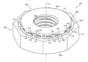
Self-Clinching Fastener
US Patent 12163548
Published December 10, 2024
Inventors: Marc Andrew O’Donnell, Burlington, CA, USA; and Michael Da Costa, Orangeville, CA, USA
Assignee: RB&W Manufacturing LLC, Streetsboro, OH, USA
A self-clinching fastener for attachment to a plastically deformable metal substrate includes a body portion with a central axis, the body portion has an annular-shaped surface extending in a direction perpendicular to the central axis The annular-shaped surface includes a first annular face, a second annular face, and a third annular face. The third annular face lies on an imaginary horizontal plane. A punch portion extends from the body portion. A plurality of spaced apart lugs encircle the punch portion. The first annular face extends from an outer peripheral surface of the punch portion in a radially outwards direction, and the second annular face is radially disposed between the first annular face and the third annular face. One of the lugs declines to the second annular face.
Fastener for Preventing Free Spinning Action During the Fastening Process
US Patent 12152622
Published November 26, 2024
Inventor: Emmanuel Carlos, El Cajon, CA, USA
Disclosed herein is a fastener for preventing free spinning action during the fastening process, in accordance with some embodiments. Accordingly, the fastener may include a fastener head and a fastener body. Further, the fastener head may include a top head surface and a bottom head surface. Further, the bottom head surface may be characterized by a bottom surface area. Further, the fastener body attached to the fastener head. Further, a first body end of the fastener body may be attached to the bottom head surface. Further, a first end cross-sectional area of the first body end may be less than the bottom surface area. Further, the fastener body may include a first body portion and a second body portion. Further, the first body portion is proximal to the first body end. Further, the second body portion proximal to a second body end of the fastener body.
Rolled Thread Screw and Rolled Thread Screw Manufacturing Method
US Patent 12152624
Published November 26, 2024
Inventor: Takeshi Saito, Gunma, Japan
Assignee: NSK Ltd., Tokyo, Japan
A rolled thread screw includes: a screw part having, on an outer circumferential part of the screw part, thread crests and thread grooves disposed alternately along an axial direction of the rolled thread screw; and a columnar part adjoining at least one of both sides of the screw part in the axial direction. An axial end surface of the columnar part is provided with: a first concave surface concave in the axial direction; a second concave surface positioned to an outer circumference of the first concave surface and being concave in the axial direction; and a salient part positioned on a boundary between the first concave surface and the second concave surface and projecting further than a bottom of the first concave surface and a bottom of the second concave surface, the salient part extending in an arc-like shape along a circumferential direction of the columnar part as viewed in the axial direction.